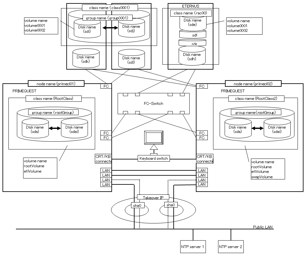
This is a design example for PRIMEQUEST. Refer to the following example when designing the PRIMEQUEST.
System configuration
Figure A.2 System configuration example
Note: The NTP server should be set to one of the following operation mode;
Maintains time that is reliable for special hardware devices such as time units and GPS units.
Uses another server that maintains time that is reliable for special hardware devices such as time units and GPS units, and uses NTP for time synchronization.
Used hardware
PRIMEQUEST x 2
FC-Switch x 1 unit
LAN card x 8
Fibre channel card x 4
Disk array unit x 2
Used software
Red Hat Enterprise Linux
PRIMECLUSTER 4.3
Multipath driver
Microsoft Internet Explorer (installed in the operation management personal computer)
Java SE Runtime Environment latest version (installed in the operation management personal computer)
System disk settings
Node name | Physical disk name | Slice number | Slice name | Size (MB) |
|---|---|---|---|---|
primecl01 | sda | 1 | / | 15374 |
2 | /boot/efi | 256 | ||
3 | swap | 2048 | ||
primecl02 | sda | 1 | / | 15374 |
2 | /boot/efi | 256 | ||
3 | swap | 2048 |
Note
When GDS is used to mirror the system disk, it uses one slice number and at least 32 MB of unused area (or swap area) on the system disk. If system disk mirroring is to be executed, consider the resources used by GDS when designing the system.
Shared disk array settings
Device name | Number of LU | Number of RAID groups | RAID level | Size |
|---|---|---|---|---|
ETERNUS | 4 | 1 | 5 | 248.2GB |
Shown below is an example of creating the Cluster Configuration Worksheet.
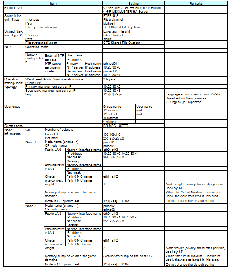
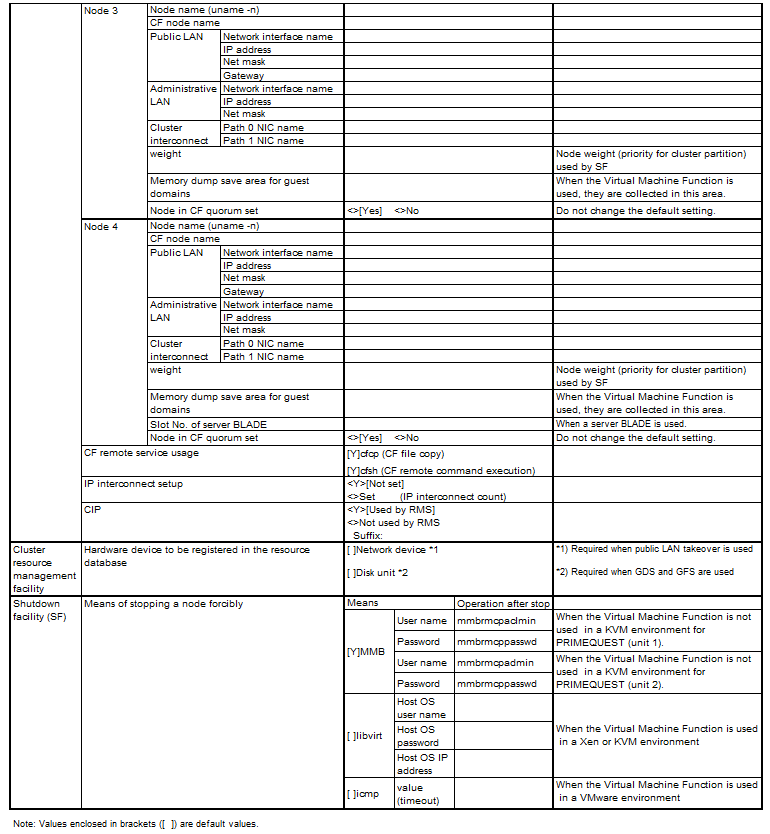
GFS: Global File Services
GDS: Global Disk Services
Shown below is an example of creating the GFS Shared File System Setup Worksheet.

GFS: Global File Services
Shown below are examples of creating the GLS Setup Worksheet.
NIC switching mode (virtual IP Takeover)
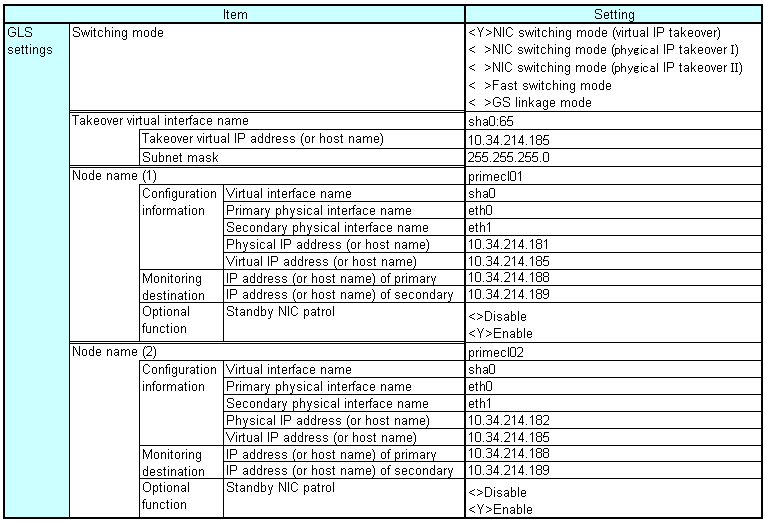
GLS: Global Link Services
NIC switching mode (physical IP takeover I)
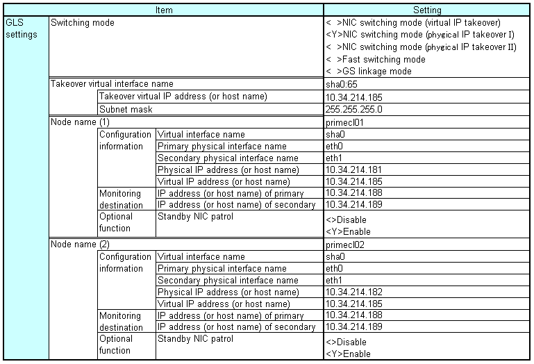
GLS: Global Link Services
NIC switching mode (physical IP takeover II)

GLS: Global Link Services
Fast switching mode
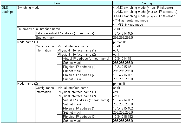
GLS: Global Link Services
GS linkage mode
Item | Setting | ||||
|---|---|---|---|---|---|
GLS | Switching mode | < >NIC switching mode (virtual IP takeover) | |||
Takeover virtual interface name | sha0:65 | ||||
Takeover virtual IP address (or host name) | 10.34.214.185 | ||||
Subnet mask | 255.255.255.0 | ||||
Node name (1) | primecl01 | ||||
Configuration information | Virtual interface name | sha0 | |||
Physical interface name (1) | eth0 | ||||
Physical interface name (2) | eth1 | ||||
IP address (or host name) (1) | 10.34.214.181 | ||||
Subnet mask (1) | 255.255.255.0 | ||||
IP address (or host name) (2) | 10.34.215.182 | ||||
Subnet mask (2) | 255.255.255.0 | ||||
Node name (2) | primecl02 | ||||
Configuration information | Virtual interface name | sha0 | |||
Physical interface name (1) | eth0 | ||||
Physical interface name (2) | eth1 | ||||
IP address (or host name) (1) | 10.34.214.183 | ||||
Subnet mask (1) | 255.255.255.0 | ||||
IP address (or host name) (2) | 10.34.215.184 | ||||
Subnet mask (2) | 255.255.255.0 | ||||
Remote host name | GS-1 | ||||
Configuration information | Virtual IP address | 10.34.215.182 | |||
IP address (1) | 10.34.214.185 | ||||
IP address (2) | 10.34.214.186 | ||||
GLS: Global Link Services
Shown below is an example of creating the System Disk Mirror Setup Worksheet.
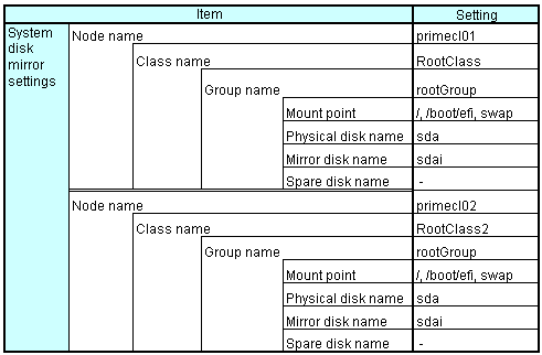
Shown below are examples of creating the GDS Configuration Worksheet.
System configuration example
For a system configuration example, set up the worksheet as shown below.
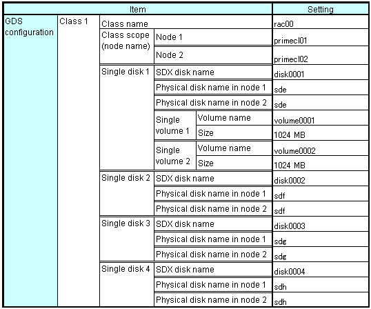
GDS: Global Disk Services
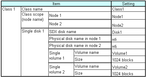
Examples of creating the GDS Configuration Worksheet are provided below.
Example 1. Managing a disk as a single disk:
In this example, single volumes Volume1 and Volume2 are created in physical disk sdj.
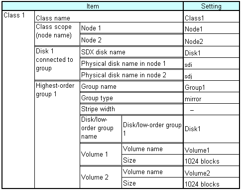
Example 2. If a disk is not mirrored but may be changed to a mirror configuration later:
In this example, mirror group Group1, which consists only of physical disk sdi, is created, and single volumes Volume1 and Volume2 are created in Group1.
Since Group1 consists of only one disk, Volume1 and Volume2 are not mirrored. If another disk is added to Group1, then Volume1 and Volume2 can be changed to a mirror configuration.
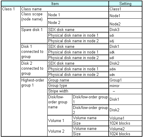
Example 3. If disk mirroring is to be executed:
In this example, mirror group Group1, which consists of physical disks sdk and sdl, is created, and mirrored volumes Volume1 and Volume2 are created in Group1.
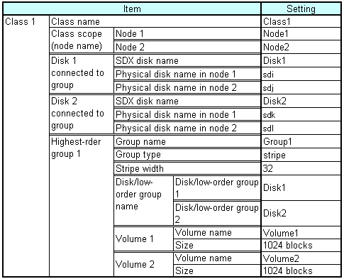
Example 4. If disk striping is to be executed:
In this example, striping group Group1, which consists of physical disks sdi and sdj, is created, and striped volumes Volume1 and Volume2 are created in Group1.
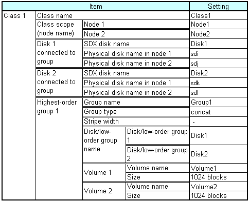
Example 5. If disk concatenation is to be executed:
In this example, concatenation group Group1, which consists of physical disks sdi and sdk, is connected, and volumes Volume1 and Volume2 are created in Group1.
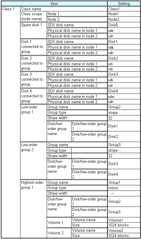
Example 6. If disk striping and mirroring are to be executed:
In this example, mirror group Group1, which consists of striping group Group2 and striping group Group3, is created, and volumes Volume1 and Volume2 are created in Group1. Striping group Group2 consists of physical disks sdg and sdi, and striping group Group3 consists of physical disks sdk and sdm.
