PRIMECLUSTER enables the following functions through connection to XSCF of SPARC M10 and M12.
Asynchronous monitoring of a node
Detects node errors immediately
Forcible stop of a failed node
Detects loss of heartbeat and stops the failed node forcibly
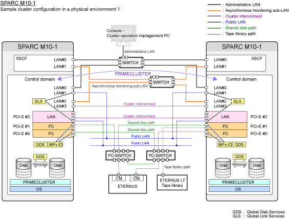
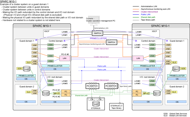
The asynchronous monitoring and forcible stop of a failed node make a communication route for XSCF redundant by using XSCF-LAN#0 and #1.
XSCF-LAN#0: Administrative LAN
XSCF-LAN#1: Asynchronous monitoring sub-LAN
The Asynchronous monitoring sub-LAN makes the path of the asynchronous monitoring and forcible stop of a failed node redundant. This LAN is connected by the other subnet differing from the administrative LAN.
By preparing the asynchronous monitoring sub-LAN, the failed node can be forcibly stopped even when an error occurs in the administrative LAN.
It is recommended that you use the asynchronous monitoring sub-LAN in a cluster configuration.
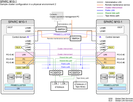
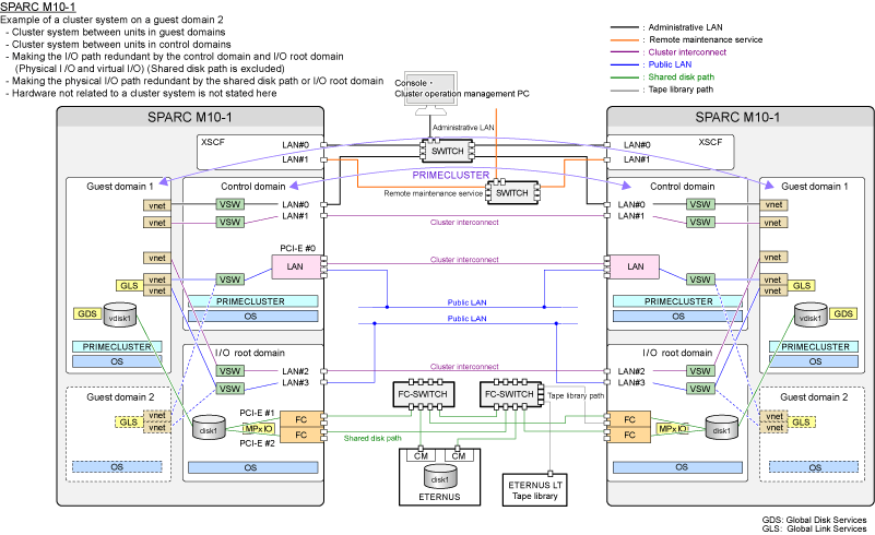
When using XSCF-LAN#1 for any purposes other than the asynchronous monitoring sub-LAN due to the system requirements or other reasons, note the following points and build a configuration without the asynchronous monitoring sub-LAN.
The communication for XSCF cannot be made redundant in this configuration. If an error occurs in the administrative LAN in this configuration, the connection to XSCF will not be available so that the asynchronous monitoring and forcible stop of a failed node cannot be done.
If an error occurs in this situation (such as a node panic or loss of heartbeat), the service cannot be switched. When one of the following messages is displayed, check the cause. If XSCF has failed or the route to XSCF has failed, replace it immediately.
SA SA_xscfsnmpg0p.so to test host <nodename> failed
SA SA_xscfsnmpg1p.so to test host <nodename> failed
SA SA_xscfsnmpg0r.so to test host <nodename> failed
SA SA_xscfsnmpg1r.so to test host <nodename> failed
SA SA_xscfsnmp0r.so to test host <nodename> failed
SA SA_xscfsnmp1r.so to test host <nodename> failed
Figure 2.22 Sample cluster configuration in a physical environment 1 (recommended configuration using the administrative LAN and asynchronous monitoring sub-LAN)

Figure 2.23 Sample cluster configuration in a physical environment 2 (configuration without using the asynchronous monitoring sub-LAN)

Figure 2.24 Sample cluster configuration in guest domains 1 (recommended configuration using the administrative LAN and asynchronous monitoring sub-LAN

Figure 2.25 Sample cluster configuration in guest domains 2 (configuration without using the asynchronous monitoring sub-LAN)
