Switching function switches a path used for communication depending on network topology changes due to network failures and recovery.
If an error is detected by the link status monitoring, the communication is continued by switching the system to the standby NIC.
If an error is detected by the network monitoring, the communication is continued in all NICs. However, once the communication path is recovered, the only one NIC can carry out the operation.
Here, describes examples in the following states:
During normal operation
In the event of NIC failures
In the event of link failures between switches
In the event of switch failures
At a switch failure recovery
During normal operation
When all NICs and switches are operated normally, a virtual NIC uses redundant NIC exclusively (NIC1: Active, NIC2: Standby) to carry out the communication.
In this case, the communication for all the remote systems is carried out in NIC1 and the status of NIC2 will be "Standby."
Figure 2.3 Communication type during normal operation

In the event of NIC failures
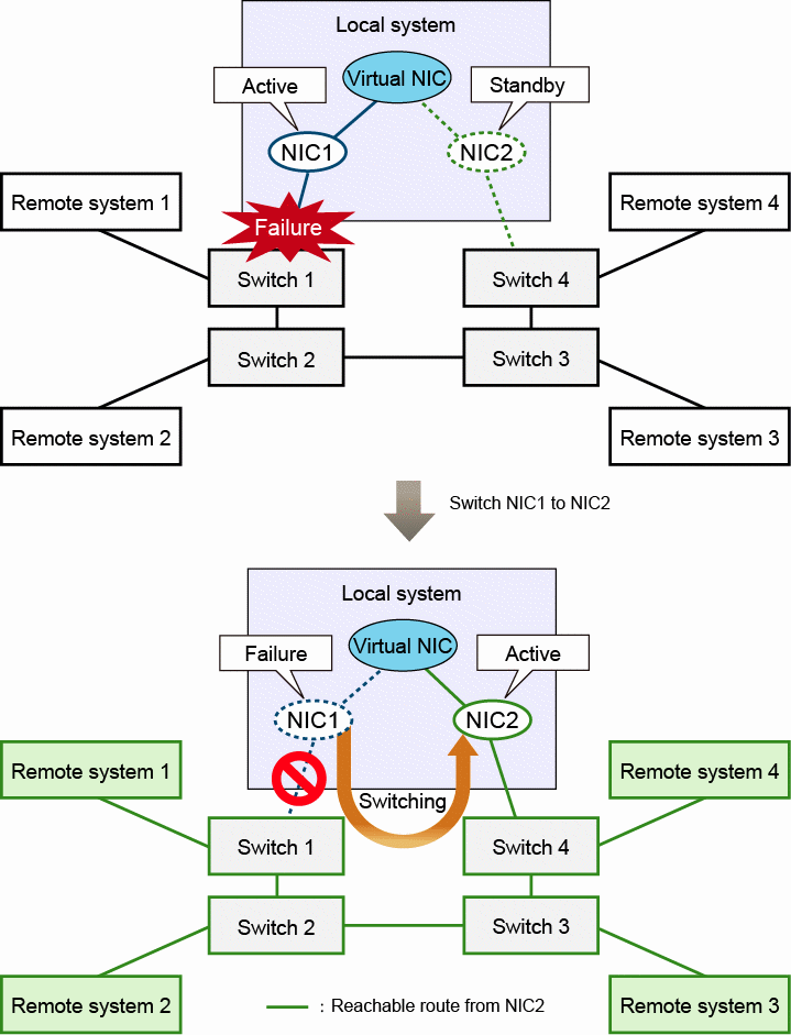
When an error occurred in NIC1 or Switch 1 of the connection target and NIC1 is in the link down state, the communication can be continued by switching NIC1 to NIC2. In this case, the communication for all the remote systems is carried out with NIC2.
Figure 2.4 Communication type in the event of NIC failures

In the event of link failures between switches
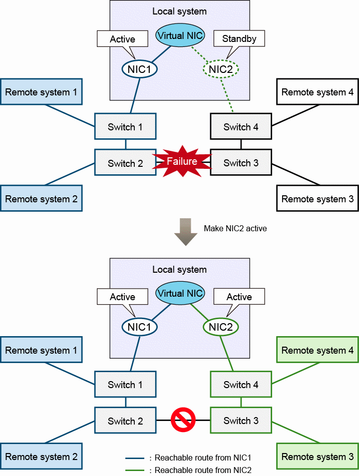
If a link error occurred between Switch 2 and Switch 3, since the network is divided into two parts, the communication for the remote systems 1 and 2 can be continued. However, the ones for 3 and 4 will be disabled. In this case, make NIC2 "Active" state in addition to NIC1 so that the communication for the remote systems 3 and 4 will be continued.
Figure 2.5 Communication type in the event of link failures between Switch 2 and 3

In the event of switch failures
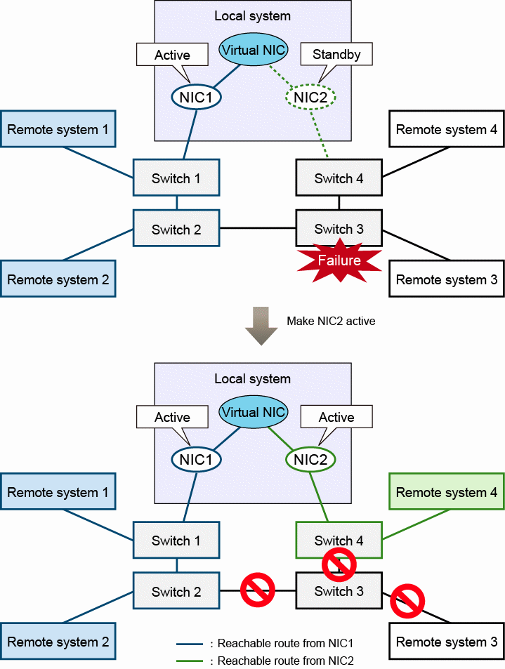
In the event of Switch 3 failures, make NIC2 "Active" state so that the communication for the remote system 4 will be continued. For the communication for the remote system 3, since there is no physical reachable path, the communication is disabled.
Figure 2.6 Communication type in the event of Switch 3 failures

At a switch failure recovery
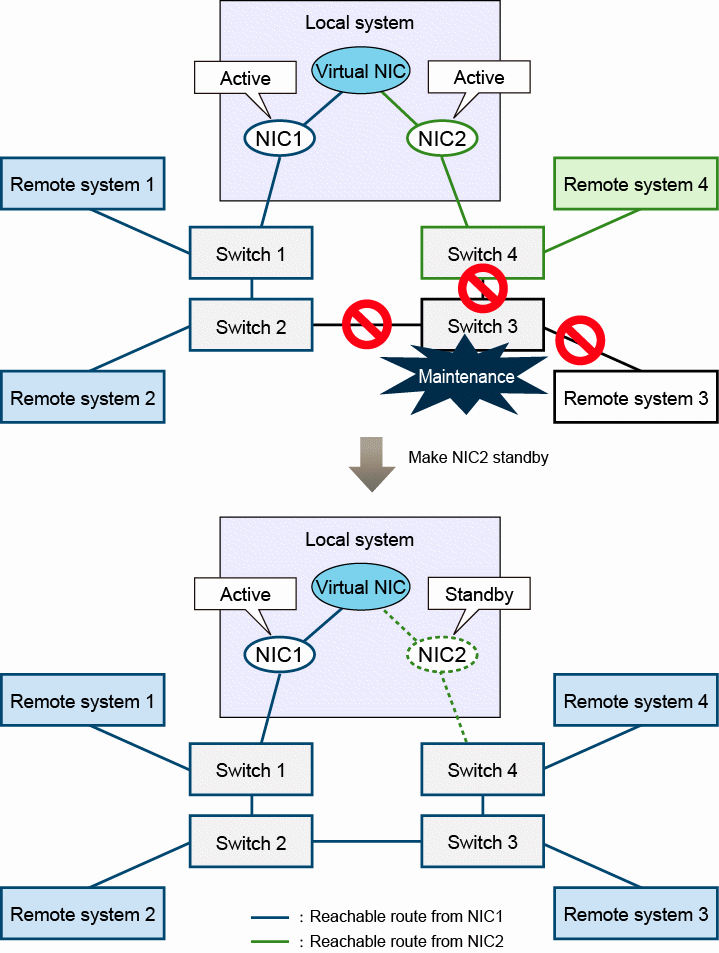
When the network disconnection is recovered by the maintenance such as replacing failed switches, return the status of NIC2 to "Standby" and the communication with all the remote systems will be carried out only in NIC1 again.
Figure 2.7 Communication type at a switch recovery
