An example of a Disaster Recovery environment system configuration is given below.
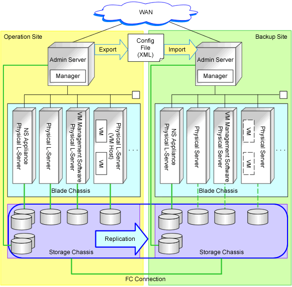
Example Disaster Recovery Environment System Configuration Containing both Physical L-Server Switchover (Physical OS) and Physical/Virtual L-Server Switchover (VM Host/VM Guest)
An example of a Disaster Recovery environment system configuration that contains both physical L-Server switchover (physical OS) and physical/virtual L-Server switchover (VM host/VM guest) is shown below:
Figure 2.14 Example Disaster Recovery Environment Containing both Physical L-Server Switchover (Physical OS) and Physical/Virtual L-Server Switchover (VM Host/VM Guest)

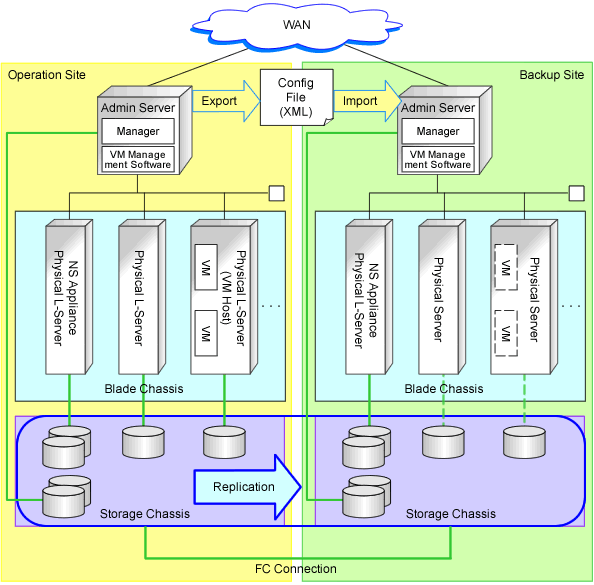
Example of System Configuration Installing VM Management Software on the Admin Server
An example system configuration with VM management software installed on the admin server is shown below:
Figure 2.15 Example of VM Management Software Installation on the Admin Server in a Disaster Recovery Environment which Contains both Physical L-Server Switchover (Physical OS) and Physical/Virtual L-Server Switchover (VM Host/VM Guest)

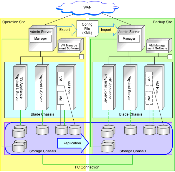
Example Disaster Recovery Environment System Configuration which Contains both Physical L-Server Switchover (Physical OS) and Virtual L-Server Switchover (VM Guest)
An example of a Disaster Recovery environment system configuration that contains both physical L-Server switchover (physical OS) and virtual L-Server switchover (VM guest) is shown below:
Figure 2.16 Example Disaster Recovery Environment which Contains both Physical L-Server Switchover (Physical OS) and Virtual L-Server Switchover (VM Guest)
