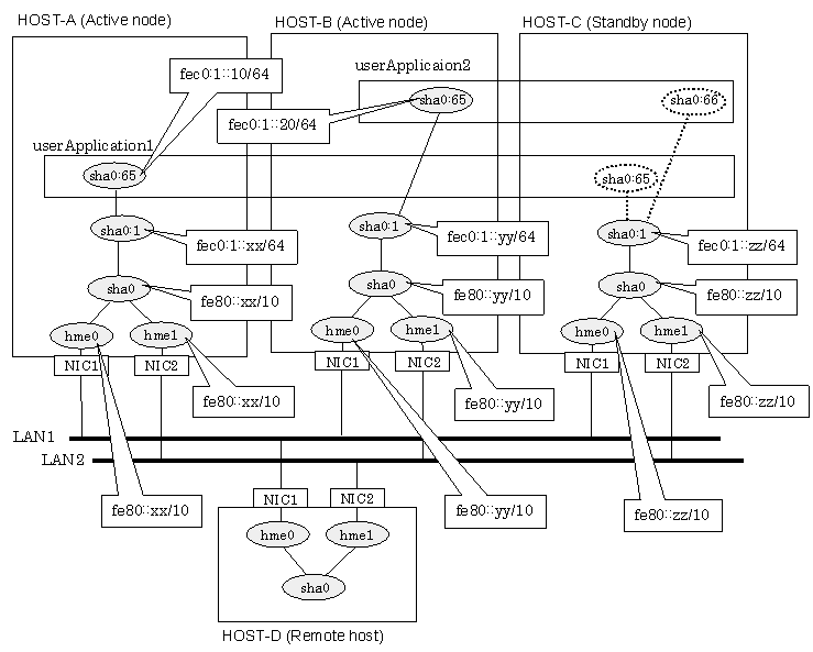
This section describes an example configuration procedure of the network shown in the diagram below.
The values for xx, yy and zz in the IP address of the figure below are assigned automatically by the automatic address configuration.
For configuring the cluster system, refer to the Cluster system manual.
In this section, description of private LAN is omitted.
The dotted line indicates that the interface is inactive.
Note
When using IPv6 address as a takeover virtual interface, it may take around 30 seconds to recover the communication after switching the node. In order to hold a communication instantly, start IPv6 routing daemon beforehand on both operating and standby nodes. For details on this issue, refer to "D.2 Trouble shooting".

[HOST-A]
1) Setting up the system
1-1) Create /etc/inet/ndpd.conf file and set the followings:
ifdefault AdvSendAdvertisements true # Every interface sends a router advertisement. prefix fec0:1::0/64 sha0 # sha0 sends Prefix "fec0:1::0/64". |
Note
In the Solaris server that runs Fast switching mode, configure two or more router as IPv6 router. If the IPv6 router breaks down, it cannot use site-local address to communicate. To prevent this, it is recommended to setup at least two IPv6 routers.
For details on /etc/inet/ndpd.conf, refer to the Solaris manual.
1-2) Create /etc/hostname6.hme0 and /etc/hostname6.hme1 files as an empty file.
1-3) Define IP addresses and hostnames in /etc/inet/ipnodes file.
fec0:1::10 v6hosta1 # Takeover virtual IP (1) fec0:1::20 v6hostb1 # Takeover virtual IP (2) |
2) Reboot
Run the following command to reboot the system. Make sure hme0 and hme1 are enabled as IPv6 interfaces after rebooting the system.
/usr/sbin/shutdown -y -i6 -g0
3) Creation of virtual interface
/opt/FJSVhanet/usr/sbin/hanetconfig create inet6 -n sha0 -m t -t hme0,hme1
4) Creation of takeover virtual interface
/opt/FJSVhanet/usr/sbin/hanethvrsc create -n sha0 -i fec0:1::10/64
[HOST-B]
1) Setting up the system
1-1) Create /etc/hostname6.hme0 and /etc/hostname6.hme1 files as an empty file.
1-2) Define takeover virtual IP addresses and hostnames in /etc/inet/ipnodes file. Defined information is the same as for HOST-A.
2) Reboot
Run the following command to reboot the system. Make sure hme0 and hme1 are enabled as IPv6 interfaces after rebooting the system.
/usr/sbin/shutdown -y -i6 -g0
3) Creation of virtual interface
/opt/FJSVhanet/usr/sbin/hanetconfig create inet6 -n sha0 -m t -t hme0,hme1
4) Creation of takeover virtual interface
/opt/FJSVhanet/usr/sbin/hanethvrsc create -n sha0 -i fec0:1::20/64
[HOST-C]
1) Setting up the system
1-1) Create /etc/hostname6.hme0 and /etc/hostname6.hme1 files as an empty file.
1-2) Define IP addresses and hostnames in /etc/inet/ipnodes file. Defined content is same as HOST-A.
Define takeover virtual IP addresses and hostnames in /etc/inet/ipnodes file. Defined information is the same as for HOST-A.
2) Reboot
Run the following command to reboot the system. Make sure hme0 and hme1 are enabled as IPv6 interfaces after rebooting the system.
/usr/sbin/shutdown -y -i6 -g0
3) Creation of virtual interface
/opt/FJSVhanet/usr/sbin/hanetconfig create inet6 -n sha0 -m t -t hme0,hme1
4) Creation of takeover virtual interface
/opt/FJSVhanet/usr/sbin/hanethvrsc create -n sha0 -i fec0:1::10/64
/opt/FJSVhanet/usr/sbin/hanethvrsc create -n sha0 -i fec0:1::20/64
[Configuration by RMS Wizard]
After completing step 4) of HOST-A, HOST-B, and HOST-C connect to the administration server using RMS Wizard, then setup the cluster environment.
To create Gls resources, select the SysNode compliant with HOST-A, HOST-B, and HOST-C. Once Gls is created, register the two Gls resources on the userApplication.
When registering on the userApplication, select the SysNode compliant with HOST-A, HOST-B, and HOST-C in the order of operation node followed by standby node. Then, register the takeover address "fec0:1::10" and "fec0:1::20".
After completing the configuration, start the userApplication to activate the takeover virtual interface on the operation node.