Solaris container
Solaris containers are location independent and complete runtime environments for applications. Each application runs in its own private environment -- without dedicating new systems -- and many applications can be tested and deployed on a single server. Solaris Zones software partitioning technology provides a virtual mapping from the application to the platform resources. Zones allow application components to be isolated from one another even though the zones share a single instance of the Solaris Operating System. The Solaris Zones partitioning technology is used to virtualize operating system services and provide an isolated and secure environment for running applications. A zone is a virtualized operating system environment created within a single instance of the Solaris Operating System.
The virtual server is referred to simply as non-global zone (hereafter, zone). Every Solaris system contains a global zone. The global zone is both the default zone for the system and the zone used for system-wide administrative control. The redundant line control function ensures network high-reliability on the zone.
Network interface of Solaris container
Solaris containers provided the following two network forms:
Shared-IP
Physical interfaces configured on the global zone are shared with non-global zones in this network form. The zone defined as ip-type=shared in the zone configuration information is applied.
Exclusive-IP
Physical interfaces are occupied by specific non-global zones in this network form. The zone defined as ip-type=exclusive in the zone configuration information is applied.
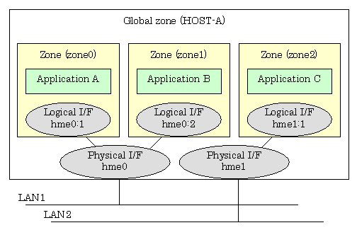
One or more IP address is allocated to each zone with shared-IP configuration of the Solaris container. The IP addresses are added to the logical interface generated on the physical interface. The logical interface is hidden from the other zones, so applications can only use the IP addresses (logical interface) allocated to the zone.
The following figure shows the network interfaces configuration example.
Figure 2.52 Network interfaces configuration example
Starting each zone from the global zone will enable the zone.
Note
IP addresses (logical interfaces) allocated to each zone are created or deleted from Solaris OS along with zone startup or stop. If physical interfaces or virtual interfaces do not exist, the zone will not be started. If you make the zone network highly reliable through redundant line control, it is necessary to activate the virtual interface before zone startup. However, the redundant line control function will be first started during system startup, so users do not have to be aware of the startup order.
In a zone with exclusive-IP of the Solaris container, physical interfaces are occupied, and functions of the IP level are available in the same manner as the global zone. In addition, allocated physical interfaces are not available from other zones. To make the network with exclusive-IP configuration highly reliable, install Redundant Line Control function in non-global zones and multiplex physical interfaces allocated in non-global zones.
The following example shows a network interface configuration for exclusive-IP of the Solaris container.
Figure 2.53 Interface configuration in an exclusive-IP zone
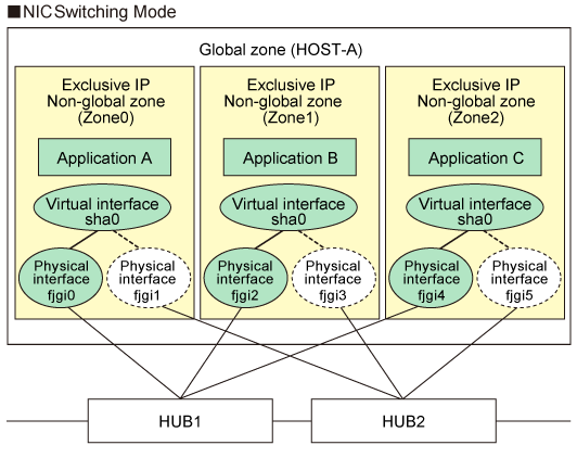
The non-global zone Zone0 is configured by specifying ip-type=exclusive, and physical interfaces fjgi0 and fjgi1 are allocated. Redundant Line Control function works on Zone0 and multiplexes fjgi0 and fjgi1 redundancy the same as the normal system. As for Zone1 and Zone2, Redundant Line Control function works on each zone in the same manner as Zone0 and multiplexes physical interfaces in the same manner as the normal system.
Redundant line control in Solaris container
The following table describes how each redundant line control function corresponds to high-reliability and GLS command capability in the global or non-global zone of the Solaris container.
Solaris container | ||||
|---|---|---|---|---|
Global zone | Non-global zone | Non-global zone | ||
Zone to install GLS | Global zone | Global zone | Non-global zone | |
Redundant line control mode | Fast switching mode | Possible | Possible | Not possible |
RIP mode | Possible | Not possible | Not possible | |
Fast switching / RIP mode | Possible | Not possible | Not possible | |
NIC switching mode | Possible | Possible | Possible | |
NIC switching mode | Possible | Possible | Possible | |
GS/SURE linkage mode | Possible | Possible | Not possible | |
Information
When you make the shared-IP zone network highly reliable through NIC switching, use physical IP takeover (operation mode "e"). If you use logical IP takeover (operation mode "d"), the redundant line control function will activate a logical IP address as a takeover IP address as well as Solaris OS will activate another logical IP address during zone startup, which means the unnecessary IP address not used by the zone will be activated. If you add the zone settings after setting logical IP takeover (operation mode "d"), it is not necessary to change it to physical IP takeover (operation mode "e").
The virtual IP address, logical IP address, and physical IP address allocated through redundant line control of the global zone can be used in the global zone only. Solaris OS will allocate IP addresses to the non-global zone during zone startup.
In non-global zones with exclusive IP, the virtual driver for Redundant Line Control function is not available. Therefore, supported redundant line control mode is only the NIC switching mode.
If Solaris 10 is installed and the patch 914233-05 or later for GLS is applied to non-global zones with exclusive IP, you can set the standby patrol function. If all redundant NICs encounter a failure without setting the standby patrol function, you need to restart monitoring by using hanetpoll off/on after NCs are restored. For details, see "7.7 hanetpoll Command."
If the patch 914233-06 or later is applied to non-global zones, the GS/SURE linkage mode is available in non-global zones (shared IP zone configuration).
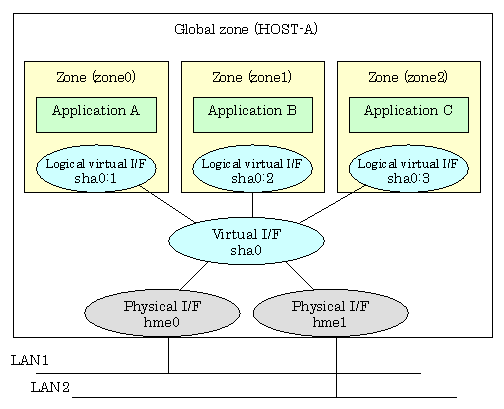
The following example shows how to configure the virtual and physical interfaces of shared-IP in fast switching mode.
The application in each zone communicates with each other using the logical/virtual interfaces that are allocated to the virtual interface. Even though an error occurs in the transmission route of the redundant physical interface (hme0 or hme1), it will never disrupt ongoing operations.
Figure 2.54 Interface structure in fast switching mode
The following example shows how to configure the virtual and physical interfaces of shared-IP in NIC switching mode.
The application in each zone communicates with each other using the logical interfaces that are allocated to the physical interfaces. Even though an error occurs in the transmission route of the redundant physical interface (hme0), the applications will be switched over to the standby interface (Ihme1) and ensures operational continuity.
Figure 2.55 Interface structure in fast switching mode

See
For details about the Solaris container, see the Solaris 10 OS manual.
Normally, the shared-IP zones of the Solaris container communicate with each other or the other systems by using the logical interfaces of the global zone that is allocated to the physical interface. If the physical interface fails, or part of the transmission route fails, communication will be disrupted.
Figure 2.56 Interface structure without redundant line control
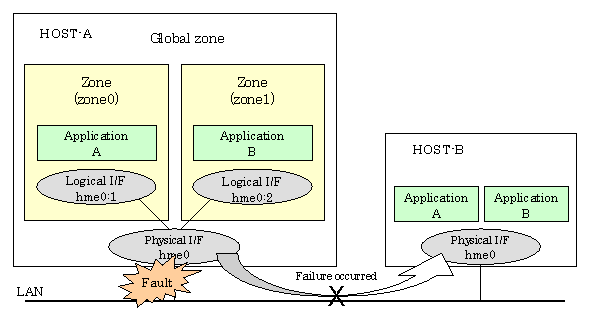
The above example shows that the Application A and B cannot communicate with each other when the transmission route fails.
The redundant line control function ensures operational continuity in the event of a transmission route failure.
Network high-reliability for shared-IP zones in fast switching mode
The following example shows how interfaces can be structured in fast switching mode.
Figure 2.57 Network reliability in fast switching mode
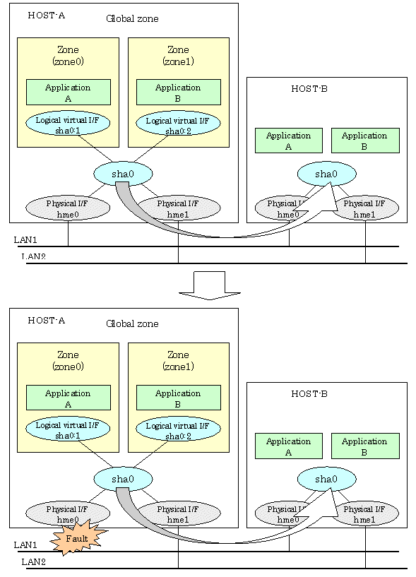
Even if a transmission route fails on either of the physical interfaces, the applications will be switched over to the logical virtual interface on the standby node through redundant line control, so operational continuity is never disrupted.
Network high-reliability for shared-IP zones in NIC switching mode
The following example shows how interfaces can be structured in NIC switching mode.
Figure 2.58 Network reliability in NIC switching mode
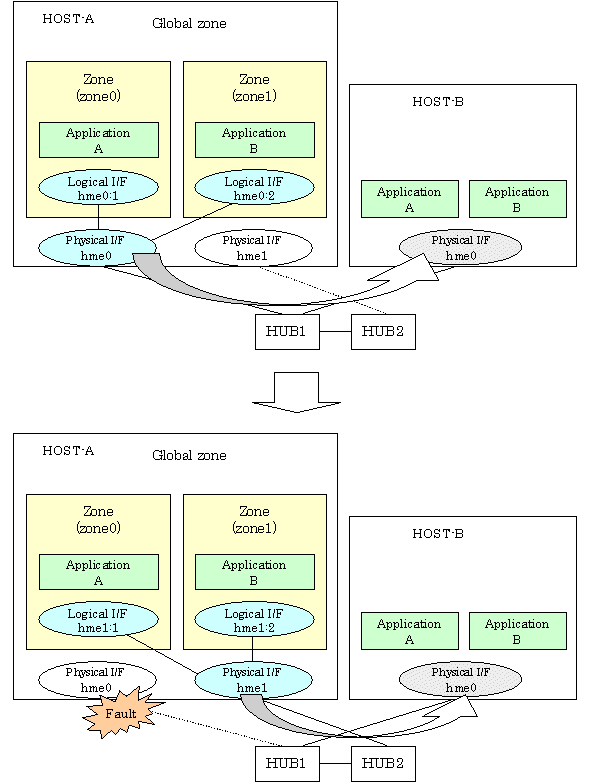
Even if a transmission route fails on the primary physical interface, the applications will be switched over to the secondary physical interface through redundant line control, so operational continuity is never disrupted.