VLAN or IP address settings for LAN switch blades, virtual switches, and L2 switches is automatically performed based on the definition information of network resources in Resource Orchestrator. For L2 switches, firewalls, and server load balancers, configuring, modifying, or deleting the definitions that include VLAN settings is automatically performed using scripts. Scripts are prepared for each model of the network devices by infrastructure administrators.
The simplified network settings will be executed when the following operations are performed:
Target | Operation | L-Server | Virtual Switch | LAN Switch Blade | L2 Switches | Ethernet Fabric Switches | Firewall | Server Load Balancer | ||
|---|---|---|---|---|---|---|---|---|---|---|
Internal Connection | External Connection | VLAN Port Profiles (*2) | Internal Connection Ports | |||||||
Network resources | Creation | - | - | - | Yes | Yes | Yes | - | - | - |
Modification | - | - | - | Yes | Yes | Yes | Yes (*6) | - | - | |
Deletion | - | Yes | Yes | - | Yes | Yes | - | - | - | |
Automatic network configuration | - | Yes | Yes | - | - | - | - | - | - | |
VM pool | Registering to Pools | - | Yes | Yes | - | - | - | - | - | - |
Virtual L-Server | Creation | Yes | Yes | Yes | - | - | - | Yes | - | - |
Modification | - | - | - | - | - | - | - | - | - | |
Addition of NICs | - | Yes | Yes | - | - | - | Yes | - | - | |
Deletion of NICs | - | - | - | - | - | - | Yes | - | - | |
Deletion | - | - | - | - | - | - | Yes | - | - | |
Physical L-Servers | Creation | Yes | - | Yes | - | Yes | - | - | - | - |
Modification | Yes | - | Yes | - | Yes | - | - | - | - | |
Deletion | - | - | Yes | - | Yes | - | - | - | - | |
L-Platform | Creation | Yes | Yes | Yes | - | Yes | - | Yes | Yes | Yes |
Modification | - | Yes | Yes | - | Yes | - | Yes | Yes | Yes | |
Deletion | - | - | Yes | - | Yes | - | Yes | Yes | Yes | |
Yes: Available
-: Not Available
*1: When using an Ethernet Fabric switch or an Ethernet Fabric switch blade which constitutes an Ethernet Fabric, the timing of auto-configuration is the same as that of the Ethernet Fabric switch.
*2: It is automatically configured when using an Ethernet fabric switch and "port profile configuration" is set to "Enable".
*3: A VLAN is automatically configured for the internal connection port used for L-Server communications according to the link between the NIC of the L-Server and the VLAN port profile.
*4: It is automatically configured when all of the following conditions are met.
- When using an Ethernet fabric switch and "port profile configuration" is set to "Enable"
- When the VM host connected to the Ethernet fabric switch is VMware or a Hyper-V virtual L-Server
*5: When automatic network configuration and automatic VLAN configuration for uplink ports are enabled, settings are automatically configured at the point when an external connection port (including an external connection port with link aggregation configured) is added.
*6: If an uplink port of the Ethernet fabric switch is added, the link between the L-Server connected to the network resource and the VLAN port profile will operate.
*7: Available when using rack mount servers and physical LAN segments have been specified.
*8: Requires a script that configures an IP address for the OS.
*9: Available when using rack mount servers.
*10: The IP address is configured or modified when the network resource is modified.
*11: Available when using virtual L-Servers.
*12: Available when using rack mount servers and physical L-Servers.
The simplifying network settings will be executed for the following scope.
Figure 2.4 Scope of Automatic Network Settings Execution (For L2 Switch)
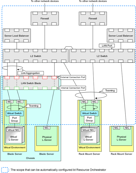
Figure 2.5 Scope of Automatic Network Settings Execution (For Ethernet Fabric Switch)
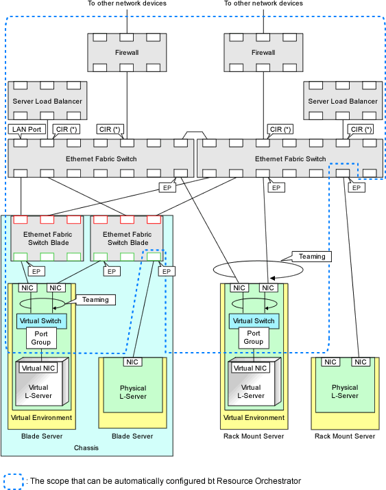
CIR: Clean Interface with Redundancy (Port that connects to an external device)
EP: End Point (Port that connects with the server)
*Note: CIR is not automatically configured.
For details on automatic network settings for virtualized environments, refer to the relevant sections explaining how to prepare and setup server virtualization software in "Appendix C Configuration when Creating Virtual L-Servers" in the "Setup Guide CE".
The following network information is hidden, depending on the network resource.
Virtual Switches
Port Groups
LAN Switch Blades
L2 Switches
Ethernet Fabric Switches
Figure 2.6 Hiding of Network Device Information (For L2 Switch)
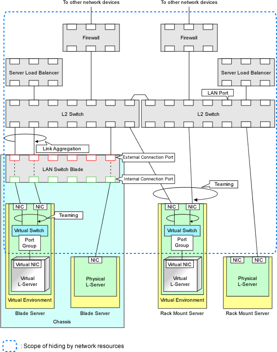
Figure 2.7 Hiding of Network Device Information (For Ethernet Fabric Switch)
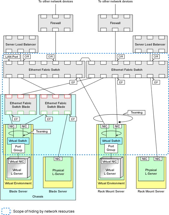
CIR: Clean Interface with Redundancy (Port that connects to an external device)
EP: End Point (Port that connects with the server)
There are two types of modes for auto-configuration of network devices.
User Customization Mode
Firewalls, server load balancers, and L2 switches are the targets.
Simple Configuration Mode
Only firewalls (NS Appliance) are the targets.
User Customization Mode
The infrastructure administrator creates the ruleset necessary to configure the definitions for the network devices (firewalls, server load balancers, and L2 switches), and registers it in Resource Orchestrator.
In Resource Orchestrator, perform auto-configuration for the target network devices using the ruleset registered by the infrastructure administrator.
For details on preparation for auto-configuration using user customization mode, refer to "Appendix F Preparing for Automatic Configuration and Operation of Network Devices".
For details on operation image of modifying configuration of firewalls using user customization mode, refer to "When an L-Platform that uses a firewall is deployed with the use of a ruleset" in "8.3.9 Setup Firewall" in the "User's Guide for Tenant Administrators CE" or "5.3.8 Setup Firewall" in the "User's Guide for Tenant Users CE".
For details on operation image of modifying configuration of firewalls using user customization mode, refer to "8.3.11 Server Load Balancer (SLB) Settings" in the "User's Guide for Tenant Administrators" or "5.3.10 Server Load Balancer (SLB) Settings" in the "User's Guide for Tenant Users".
Simple Configuration Mode
The infrastructure administrator is not required to create the rulesets necessary for configuring definitions for network devices (firewalls) in advance.
In Resource Orchestrator, it is possible to easily perform auto-configuration by using the defined definitions.
Simple configuration mode enables deployment of L-Platforms using firewalls, without using rulesets.
For details on the logical network configuration realized using simple configuration mode, the target devices, or configuration details, refer to "Appendix I Auto-configuration and Operations of Network Devices Using Simple Configuration Mode".
For details on operation image of modifying configuration of firewalls using simple configuration mode, refer to "When an L-Platform that uses a firewall is deployed without the use of a ruleset" in "8.3.9 Setup Firewall" in the "User's Guide for Tenant Administrators CE" or "5.3.8 Setup Firewall" in the "User's Guide for Tenant Users CE".
Auto-configuration Timing and Images
This section explains auto-configuration timing and images.
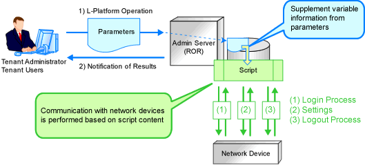
Automatic configuration of firewalls and server load balancers when creation, modification, or deletion of an L-Platform is performed
The detailed timing is as follows:
When an L-Platform is created from an L-Platform template that includes a network device (firewall or server load balancer)
When L-Server addition or deletion is performed for an L-Platform
When the settings of a network device (firewall or server load balancers) in an L-Platform are modified
When an L-Platform created from an L-Platform template that includes a network device (firewall or server load balancer) is deleted
Automatic configuration for L2 switches when creation, modification, or deletion of an network resource is performed
Automatic configuration for L2 switches when creation or modification of a physical L-Server is performed on rack mount servers
Figure 2.8 Network Device Automatic Configuration Image
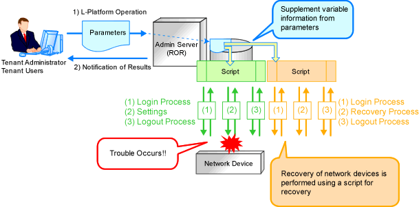
Recovery (deletion of incomplete settings, etc.) of network devices can be performed by preparing a recovery script in advance in case automatic configuration of network devices fails.
Figure 2.9 Network Device Automatic Configuration Image (Recovery Process)
The following files are available as network device (firewall, server load balancer and L2 Switch) configuration files.
Network device configuration files
A configuration file containing settings related to communication, such as address and VLAN information of devices and interfaces, and rules for firewalls and server load balancers
Network device environment files
Files required for the operation of devices such as CA certificates, user authentication databases and user customized information (excluding network device configuration files)
In this product, a function which manages device configuration files using generations is offered. Using this function modification changes can be checked and restoration of configurations can be performed easily when network devices are exchanged.
The following features are provided by the network device configuration file management function.
Backing up and restoration of configuration files
Network device configuration files can be backed up by this product and managed using generations.
Further, the latest configuration files which already backed up can be restored to network devices.
Export of configuration files
The files that are backed up and managed using generations can be exported from the manager.
Backing up and restoration of environment files
Network device configuration files can be backed up to this product.
Further, backed up environment files can be restored to network devices.
Export of environment files
The backed up files can be exported to the infrastructure admin's terminal.
Registration of external server information
For network devices which do not have an ftp server, the information of an external ftp server, which is used for backing up and restoration of network devices, can be registered.
Specify this external server in the network configuration information (XML definition) file when registering the network device.
This section provides a brief overview of simple network monitoring.
Visualize Networks (NetworkViewer/Network Map Functions)
For PRIMERGY BX servers, Resource Orchestrator provides a NetworkViewer and a Network Map function, which helps visualize and relate physical networks (between servers and LAN switches) together with virtualized networks (from VLANs or virtual switches used in server virtualization software). The NetworkViewer and the Network Map provides the following features:
Automatic detection and display of network connections (topology) and link statuses between heterogeneous network resources.
Facilitates overall network consistency diagnostics and identification of the resources (physical and virtual) affected by a network issue.
Displays comprehensive content that can be used in communication between server and network administrators, thus smoothing out coordination between the two parties.
For details on differences between the NetworkViewer and Network Map functions, refer to "Table 2.5 Functions Available for LAN Switches" in "2.2 Function Overview" in the "Design Guide VE".
Note
For VMware virtual switches, network links are only displayed when using the standard switches.
When using switches other than the standard switches, such as distributed virtual switches, those virtual switches and the network links are not displayed.
Status Monitoring
Resource Orchestrator monitors the status of network devices (Firewalls, server load balancers, and L2 switches) in order to automatically perform network settings for them.