If the NIC and network resources are connected when an L-Server is created, the following settings matching the network resource definition will be registered automatically for the VM host that the L-Server will operate on.
LAN switch blade (when using blade servers)
When using a LAN switch blade in switch mode or end-host mode, a VLAN is configured on the internal connection port.
When creating a network resource, a tagged VLAN is automatically configured on the port of the LAN switch blade specified in the uplink port, using the following procedure.
From the GUI:
In the [Create a network resource] dialog, check the [Automatically configure VLANs for the uplink ports.] checkbox.
From the Command-line:
In the XML definition for the network resource, specify "true" for vlanautosetting (Automatic VLAN configuration for uplink ports).
Virtual switches and port groups
If the required network resources do not exist, they are automatically created. A redundant NIC configuration will be configured.
If it already exists, the virtual switch and port group are used.
When the user configures the network automatically using an arbitrary physical NIC, define the physical NIC to be used in the server NIC definition file, and then specify the physical LAN segment in the server NIC definition from the network resource.
This enables automatic network configuration even in configurations using an arbitrary physical NIC.
To reflect the physical NIC configuration specified in the server NIC definition file on Resource Orchestrator, use the rcxadm nicdefctl commit command.
In addition, when using rack mount and tower servers, automatic network configuration including the configuration using an arbitrary physical NIC is possible by defining the physical NIC to be used in the server NIC definition file and then specifying the physical LAN segment defined in the server NIC definition from the network resource.
VM guests
VM guests are connected to port groups. If an image is specified, the IP address is automatically configured.
In environments using the clustering function of VM management software, in order to enable the migration of VM guests and operation using the HA function, settings for LAN switch blades, virtual switches, and port groups are performed automatically for all VM hosts comprising the cluster.
When not configuring the tagged VLAN automatically for the uplink port of network resources, use the ROR console to configure the VLAN settings of uplink ports. Right-click the LAN switch in the server resource tree, and select [Modify]-[Network Settings] from the popup menu.
For details, refer to "5.4.4 Configuring VLANs on LAN Switch Blades" in the "User's Guide for Infrastructure Administrators (Resource Management) CE".
See
For details on the server NIC definitions, refer to "14.11 Server NIC Definition" in the "Reference Guide (Command/XML) CE".
For details on the nicdefctl command, refer to "5.15 rcxadm nicdefctl" in the "Reference Guide (Command/XML) CE".
For details on how to configure VLAN settings of LAN switch blade uplink ports, refer to "5.4.4 Configuring VLANs on LAN Switch Blades" in the "User's Guide for Infrastructure Administrators (Resource Management) CE".
Note
After creating an L-Server, if VM hosts are added to the cluster afterwards, Resource Orchestrator network settings are not performed automatically.
Perform the same settings as the existing VM hosts in the cluster configuration for the LAN switch blades and virtual switches of the additional VM hosts.
For the gateway address, set the IP address of the existing node.
Default Blade Server Configuration to Support Automation of Network Configuration in Resource Orchestrator
Show the default blade server configuration to support automation of network configuration in Resource Orchestrator (server blade, specification of uplink port for network resource, correspondence relation of numbers of LAN switch blade and physical network adapter, etc.) in the following list. When there are no server NIC definitions, for network auto-configuration, the physical network adapter within the server blade is selected according to this list.
Server Blade | Specification of Uplink Port | LAN Switch Blade to Use | Physical Network Adapter Number (*4) |
|---|---|---|---|
BX920 S1 | CB1 and CB2, or no specification for uplink port | PY-SWB102(PG-SW111) | 3,4 |
PY-SWB101(PG-SW201) | 1,2 | ||
CB3 and CB4 | PY-SWB101(PG-SW201) | 5,6 | |
CB5 and CB6 | PY-SWB104(PG-SW109) | 9,10 | |
CB7 and CB8 | PY-SWB102(PG-SW111) | 11,12 | |
PY-SWB101(PG-SW201) | 9,10 | ||
BX924 S2 | CB1 and CB2, or no specification for uplink port | PY-SWB101(PG-SW201) | 1,2 |
CB3 and CB4 | PY-SWB101(PG-SW201) | 3,4 | |
CB5 and CB6 | PY-SWB104(PG-SW109) | 7,8 | |
CB7 and CB8 | PY-SWB102(PG-SW111) | 9,10 | |
PY-SWB101(PG-SW201) | 7,8 | ||
BX960 S1 | CB1 and CB2, or no specification for uplink port | PY-SWB101(PG-SW201) | 11,12 |
CB3 and CB4 (*2) | PY-SWB101(PG-SW201) | 3,4 | |
CB5 and CB6 (*3) | PY-SWB104(PG-SW109) | 7,8 | |
CB7 and CB8 (*3) | PY-SWB102(PG-SW111) | 9,10 | |
CB7 and CB8 (*3) | PY-SWB101(PG-SW201) | 7,8 |
*1: When installing a PY-SWB104 (PG-SW109) on CB1 or CB2, set the transmission speed at the down link port of PY-SWB104 (PG-SW109) to 1 Gbps. For details on how to configure the settings, refer to the corresponding hardware manual.
*2: A LAN expansion card is mounted in expansion slot 1.
*3: A LAN expansion card is mounted in expansion slot 2.
*4: Use each physical network adapter, by performing redundancy using teaming.
Server Blade | Specification of Uplink Port | LAN Switch Blade to Use | Physical Network Adapter Number (*3) |
|---|---|---|---|
BX920 S2 | CB1 and CB2 (*1), or no specification for uplink port | PY-SWB102(PG-SW111) | 3,7 |
PY-SWB101(PG-SW201) | 2,6 | ||
CB3 and CB4 | PY-SWB101(PG-SW201) | 9,10 | |
BX924 S2 | CB1 and CB2 (*1), or no specification for uplink port | PY-SWB101(PG-SW201) | 2,4 |
CB3 and CB4 | PY-SWB101(PG-SW201) | 7,8 |
*1: The same LAN switch blade model should be mounted in CB1 and CB2.
*2: When installing a PY-SWB104 (PG-SW109) on CB1 or CB2, set the transmission speed at the down link port of PY-SWB104 (PG-SW109) to 1 Gbps. For details on how to configure the settings, refer to the corresponding hardware manual.
*3: Use each physical network adapter, by performing redundancy using teaming.
Server Blade | Specification of Uplink Port | LAN Switch Blade to Use | Physical Network Adapter Number (*) |
|---|---|---|---|
BX600 series servers | NET1 and NET2, or no specification for uplink port | PG-SW107 | 3,4 |
NET3 and NET4 | PG-SW104 | 7,8 |
* Note: Use each physical network adapter, by performing redundancy using teaming.
The numbers of physical network adapters given above can be checked in "Network Properties" on the [Resource Details] tab.
When the LAN switch blade is in IBP mode, the same physical network adapter as in the case of "no specification for uplink port" in the list above is selected.
When the user configures the network automatically using an arbitrary physical NIC, define the physical NIC to be used in the server NIC definition file, and specify the physical LAN segment in the server NIC definition from the network resource.
To reflect the physical NIC configuration specified in the server NIC definition file on Resource Orchestrator, use the rcxadm nicdefctl commit command. This enables automatic network configuration even in configurations using an arbitrary physical NIC.
However, when using server NIC definitions, the operation must be performed from the command-line.
In addition, when using rack mount and tower servers, automatic network configuration including the configuration using an arbitrary physical NIC is possible by defining the physical NIC to be used in the server NIC definition file and then specifying the physical LAN segment defined in the server NIC definition from the network resource.
See
For details on the server NIC definitions, refer to "14.11 Server NIC Definition" in the "Reference Guide (Command/XML) CE".
For details on the nicdefctl command, refer to "5.15 rcxadm nicdefctl" in the "Reference Guide (Command/XML) CE".
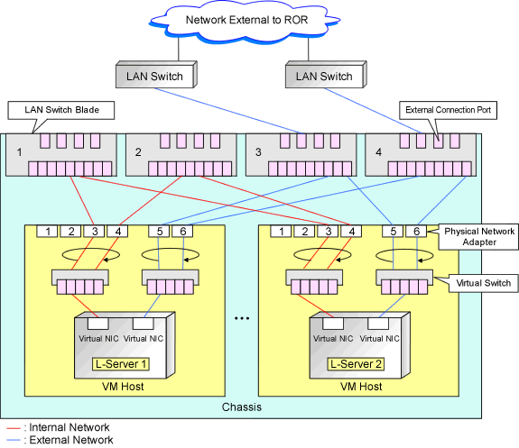
In the diagram, the default blade server configurations as described in the following configuration example when using a PRIMERGY BX900 S1 chassis are shown.
Server blades | BX920 S2 |
Specification of uplink port | CB1 and CB2 |
LAN switch blade to use | PY-SWB103(PG-SW112) |
Server blades | BX920 S2 |
Specification of uplink port | Both "no specification for uplink port" and "CB3 and CB4" are specified |
LAN switch blade to use | PY-SWB104(PG-SW109) |
Figure C.1 Blade Server Diagram of Configuration Example 1
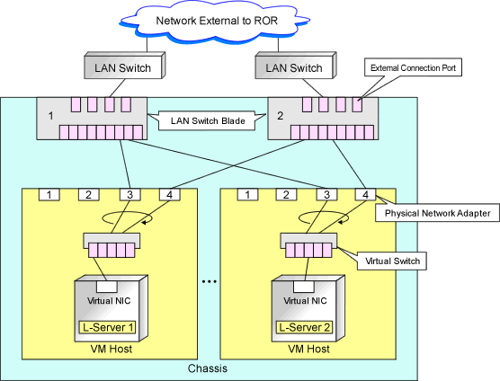
Figure C.2 Blade Server Diagram of Configuration Example 2