Using the arrow button ![]() in the toolbar, you can draw arrows to connect nodes. Your process definition must have at least two nodes before you can draw any connecting arrows. You cannot draw an arrow that does not connect two nodes.
in the toolbar, you can draw arrows to connect nodes. Your process definition must have at least two nodes before you can draw any connecting arrows. You cannot draw an arrow that does not connect two nodes.
To add an arrow:
Click the Arrow button in the toolbar.
Move the cursor to the arrow's source node. From the cursor's shape you can recognize where you can start drawing the arrow.
Drag the cursor from the source node to the target node.
Every node has several connection points for the arrow to snap in. You can see the connection points when you point to the edges of the node.
The arrow cursor is still active and you can draw as many arrows as you wish. To disable it, press the <Esc> key or click the Select button in the toolbar.
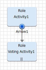
Figure 6.9 Adding an Activity Node arrow
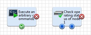
Adding an operation component arrow
When you select an operation component from the palette and move it to the Process Definition Editor, operation components with connection points that have symbols indicating normal or abnormal attached are positioned.
The number and positioning of the symbols depends on the type of operation component.
Figure 6.10 Adding an operation component arrow
Put the cursor over the symbol to see a tool tip displaying the default name of the arrow.
The names of arrows are the default names defined for each type of operation component. This arrow name can be changed later.
If there are not enough arrows, a message indicating this appears in the Problems view when you save the process definition or click the Validate button.
Arrows cannot be added on sides without symbols.
No more arrows can be added once arrows have been added to all symbols. If further branching is required, connect a Conditional node or Complex Conditional node to the symbol.
Irrespective of the execution results of the operation component node (normal or abnormal), you can still draw arrows for the same succeeding node.
Operation component nodes positioned in the process definition by older versions of Studio will be displayed as they were in the older version. However, only one arrow may be added to operation component nodes of older versions.
The operation component nodes of older versions and operation component nodes with symbols may be used together.
If the version of this product is later than V15, then the operation components positioned with Studio will all be operation component nodes with symbols. You may not position operation component nodes using the format of older versions.
Operation component nodes positioned in the process definition by older versions of Studio may not be updated to operation component nodes with symbols. To use the operation component nodes with symbols, first delete the operation component nodes from the older version, then position the new operation component node.
The types of symbols and their meaning are as follows:
Symbol | Symbol | Meaning |
|---|---|---|
|
| Indicates selection. |
|
| Indicates normal. |
|
| Indicates failure or error. |