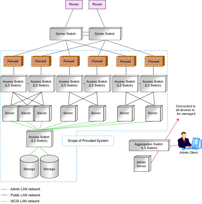
Managed devices (server machines and network devices) are connected using the public LAN.
Managed devices (server machines and storage units) are connected using the iSCSI LAN.
Design of an iSCSI LAN is required to connect the iSCSI-enabled storage devices and servers to which physical L-Servers will be deployed.
Information Necessary for Designing a Public LAN
When designing a public LAN, the following information needs to be defined beforehand:
Estimate the number of required devices (servers and network devices).
Define the required devices based on the designed virtual system.
The number of required devices should be estimated based on the following information:
Performance requirements assumed during designing of the virtual system
The number of planned tenants defined during designing of the admin LAN
Specifications of devices to be used
Estimate the specifications (including supported functions) required for the devices.
Define the number of VLAN IDs for use on the public LAN.
As the upper limit of the number of VLAN IDs varies depending on the device, when using devices that connect with both the admin and public LANs, ensure that the number does not exceed the maximum.
Define the VLAN ID range for use on the public LAN.
As available VLAN ID range varies depending on the device, when using the devices that connect with both the admin and public LANs, ensure that ranges do not overlap.
Define the IP address range of the public LAN.
Decide whether to configure communication route redundancy.
Whether to configure communication route redundancy should be decided based on the designed virtual system.
Define the LAN ports or NICs to use.
Define one of the following:
For network devices, LAN ports other than the ones assigned to the admin LAN.
For servers, NIC ports other than the ones assigned to the admin LAN.
When planning to use a rack mount server or tower server as a physical L-Server, define the following information:
The NIC number of the rack mount server or tower server
Check the alignment sequence and number of NICs on the back of the rack mount or tower servers, and then choose the numbers of NICs to be specified when creating a physical L-Server, by consecutive numbers starting with 1 (such as 1, 2,...).
As the admin LAN uses small NIC numbers ("1" for non-redundant admin LANs or "1-2" for redundant LANs), ensure NICs with larger numbers are used.
Information
For blade servers, depending on the model of LAN switch blade used in the same chassis, certain network interfaces may not be available.
In this case, add expansion NICs and a LAN switch blade, or share the NIC used for the admin LAN.
All network interfaces shared between the admin LAN and the public LAN for managed servers should be configured with tagged VLAN IDs.
The NICs that are unavailable depend on the combination of the mounted LAN switch blade and blade server. For details, refer to the manual of the LAN switch blade and blade server.
Information Necessary for Designing an iSCSI LAN
When designing an iSCSI LAN, the following information needs to be defined beforehand:
Define a NIC on the server used for an iSCSI LAN.
Both single and multi-path configurations are available.
For each tenant, define a network address and a VLAN ID for use on the iSCSI LAN.
Define whether to connect external switches between ETERNUS storage and LAN Switch Blades, or NetApp storage and LAN switch blades.
Define whether to use multi-tenant functions on ETERNUS storage or NetApp storage.
Define an IQN to be used for the NIC of the server.
Decide a network address to be used for the port of the storage.
IQN set to storage is decided. (IQN used in NIC on the server side is used.)
Define the use of authentication on iSCSI communication. When using authentication, define the authentication information.
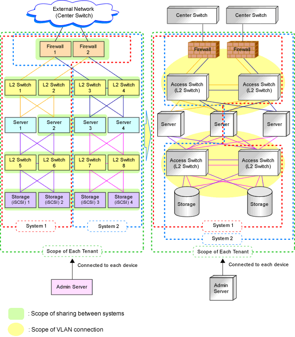
Determine the physical network configuration by defining devices necessary for the public LAN and iSCSI LAN that meet the requirements for the designed virtual system.
A sample image of virtual systems and the corresponding physical network configuration is shown below:
Figure 9.7 Sample Image of Virtual Systems and the Corresponding Physical Network Configuration

By defining how many virtual systems should be configured for each tenant and how many tenants are to be prepared, the required number of devices can be determined, making the overall configuration clear.
An example of the overall configuration of the physical system is shown below:
Figure 9.8 Example of Overall Physical Network Configuration
