In GS linkage mode, you need to set the following monitoring destination. Use the "hanetobserv create" command to set the monitoring destination. For more details on how to make settings, see "7.15 hanetobserv Command".
Virtual IP address and real IP address of the target
Physical IP addresses and takeover virtual IP addresses of other nodes that make up the cluster (applied only for the cluster configuration using PCL).
1) Setting the target monitoring
Specify the real IP address and virtual IP address of the target. GLS monitors the real IP address that has been set by using ping. In addition, based on these settings, GLS switches the virtual IP address between nodes of the target and monitors the network.
This section describes settings when the targets have the following configurations:
Single configuration
Hot-standby (One virtual IP)
Hot-standby (Two virtual IPs)
Load sharing configuration (When virtual IPs are activated on all Global Servers)
Load sharing configuration (When there is any Global Server in which virtual IP is not activated)
Use the "hanetobserv" command to register the virtual IP address and real IP address of the target.
# /opt/FJSVhanet/usr/sbin/hanetobserv create -n GS -i 192.168.110.10 -t 192.168.10.10,192.168.20.10 |
Check the settings.
# /opt/FJSVhanet/usr/sbin/hanetobserv print [ Standard Polling Parameter ] interval(s) = 5 sec times(c) = 5 times idle(p) = 60 sec repair_time(b) = 5 sec fail over mode(f) = YES Destination Host Virtual Address (Router Address+)NIC Address +----------------+-------------------+--------------------------------+ GS 192.168.110.10 192.168.10.10,192.168.20.10 |
Use the "hanetobserv" command to register the virtual IP address and real IP address of the target. Set the same name, rather than a different name, with the "-n" option for each node when you set the nodes comprising the cluster.
# /opt/FJSVhanet/usr/sbin/hanetobserv create -n GS -i 192.168.110.10 -t 192.168.10.10,192.168.20.10 # /opt/FJSVhanet/usr/sbin/hanetobserv create -n GS -i 192.168.110.10 -t 192.168.10.20,192.168.20.20 |
Check the settings.
# /opt/FJSVhanet/usr/sbin/hanetobserv print
[ Standard Polling Parameter ]
 interval(s)        =   5 sec
 times(c)           =   5 times
 idle(p)            =  60 sec
 repair_time(b)     =   5 sec
 fail over mode(f)  = YES

 Destination Host Virtual Address     (Router Address+)NIC Address
+----------------+-------------------+--------------------------------+
 GS               192.168.110.10      192.168.10.10,192.168.20.10
192.168.10.20,192.168.20.20 |
Figure 3.19 Hot-standby (Two virtual IPs)
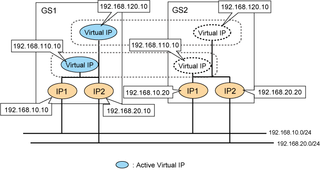
Use the "hanetobserv" command to register the virtual IP address and real IP address of the target. Set the same name, rather than a different name, with the "-n" option for each node when you set the nodes comprising the cluster.
# /opt/FJSVhanet/usr/sbin/hanetobserv create -n GS -i 192.168.110.10 -t 192.168.10.10,192.168.20.10 # /opt/FJSVhanet/usr/sbin/hanetobserv create -n GS -i 192.168.110.10 -t 192.168.10.20,192.168.20.20 # /opt/FJSVhanet/usr/sbin/hanetobserv create -n GS -i 192.168.120.10 -t 192.168.10.10,192.168.20.10 # /opt/FJSVhanet/usr/sbin/hanetobserv create -n GS -i 192.168.120.10 -t 192.168.10.20,192.168.20.20 |
Check the settings.
# /opt/FJSVhanet/usr/sbin/hanetobserv print
[ Standard Polling Parameter ]
 interval(s)        =   5 sec
 times(c)           =   5 times
 idle(p)            =  60 sec
 repair_time(b)     =   5 sec
 fail over mode(f)  = YES

 Destination Host Virtual Address     (Router Address+)NIC Address
+----------------+-------------------+--------------------------------+
 GS               192.168.110.10      192.168.10.10,192.168.20.10
                                      192.168.10.20,192.168.20.20
                  192.168.120.10      192.168.10.10,192.168.20.10
192.168.10.20,192.168.20.20 |
Figure 3.20 Load sharing configuration (When virtual IPs are activated on all Global Servers)
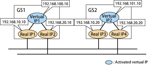
Use the "hanetobserv" command to register the virtual IP address and real IP address of the target. Set a combination of a virtual IP address and a physical IP address per GS in which every virtual IP address is activated.
# /opt/FJSVhanet/usr/sbin/hanetobserv create -n GS1 -i 192.168.100.10 -t 192.168.10.10,192.168.20.10 # /opt/FJSVhanet/usr/sbin/hanetobserv create -n GS2 -i 192.168.101.10 -t 192.168.10.20,192.168.20.20 |
Check the settings.
# /opt/FJSVhanet/usr/sbin/hanetobserv print [ Standard Polling Parameter ] interval(s) = 5 sec times(c) = 5 times idle(p) = 60 sec repair_time(b) = 5 sec fail over mode(f) = NO Destination Host Virtual Address (Router Address+)NIC Address +----------------+-------------------+--------------------------------+ GS1 192.168.100.10 192.168.10.10,192.168.20.10 GS2 192.168.101.10 192.168.10.20,192.168.20.20 |
Figure 3.21 Load sharing configuration (When there is any GS in which virtual IP is not activated)
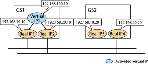
Use the "hanetobserv" command to register the virtual IP address and real IP address of the target. Set a combination of any activated virtual IP address and a GS physical IP address with non-activated virtual IP address.
If physical IP addresses of several Global Servers are set for a single virtual IP address, the GS with the physical IP address set first is recognized as communication target of GLS.
# /opt/FJSVhanet/usr/sbin/hanetobserv create -n GS -i 192.168.100.10 -t 192.168.10.10,192.168.20.10 # /opt/FJSVhanet/usr/sbin/hanetobserv create -n GS -i 192.168.100.10 -t 192.168.10.20,192.168.20.20 |
Check the settings.
# /opt/FJSVhanet/usr/sbin/hanetobserv print
[ Standard Polling Parameter ]
 interval(s)        =   5 sec
 times(c)           =   5 times
 idle(p)            =  60 sec
 repair_time(b)     =   5 sec
 fail over mode(f)  = NO

 Destination Host Virtual Address     (Router Address+)NIC Address
+----------------+-------------------+--------------------------------+
 GS               192.168.100.10      192.168.10.10,192.168.20.10
192.168.10.20,192.168.20.20 |
2) Setting PCL monitoring for other nodes
If the local system is running on a clustered system, it switches a node when GS system (remote host) stops. During this process, if no response is returned from any of the defined monitored remote system by executing "hanetobserv" command, it is recognized as a local NIC failure and it switches the node. Moreover, even though all the GS system (remote host) stops operating, all monitored remote system does not return responses, and there occurred an unnecessary switching. To avoid this, it is possible to interoperate operational node and standby node to monitor network failures. So that if all the remote system stops operating, it does not mistakenly switch the node.
If operating the cluster, use the "hanetobserv" command to monitor from both operational node and standby command. Keep in mind that since it is necessary to identify the remote node from both operational and standby node, a take-over IP address must be used for a virtual IP address.
Figure 3.22 Cluster system
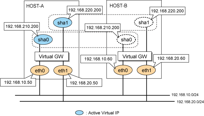
Use the "hanetobserv" command to register the virtual IP address and real IP address of the target. Set the name of another node in a cluster configuration in the "-n" option.
Settings on HOST-A # /opt/FJSVhanet/usr/sbin/hanetobserv create -n HOST-B -i 192.168.210.200 -t 192.168.10.60,192.168.20.60 # /opt/FJSVhanet/usr/sbin/hanetobserv create -n HOST-B -i 192.168.220.200 -t 192.168.10.60,192.168.20.60 Settings on HOST-B # /opt/FJSVhanet/usr/sbin/hanetobserv create -n HOST-A -i 192.168.210.200 -t 192.168.10.50,192.168.20.50 # /opt/FJSVhanet/usr/sbin/hanetobserv create -n HOST-A -i 192.168.220.200 -t 192.168.10.50,192.168.20.50 |
Check the settings.
Settings on HOST-A
# /opt/FJSVhanet/usr/sbin/hanetobserv print
[ Standard Polling Parameter ]
interval(s)        =   5 sec
 times(c)           =   5 times
 idle(p)            =  60 sec
 repair_time(b)     =   5 sec
 fail over mode(f)  = YES

 Destination Host Virtual Address     (Router Address+)NIC Address
+----------------+-------------------+--------------------------------+
 HOST-B             192.168.210.200     192.168.10.60,192.168.20.60
                    192.168.220.200     192.168.10.60,192.168.20.60

Settings on HOST-B
# /opt/FJSVhanet/usr/sbin/hanetobserv print
[ Standard Polling Parameter ]
 interval(s)        =   5 sec
 times(c)           =   5 times
 idle(p)            =  60 sec
 repair_time(b)     =   5 sec
 fail over mode(f)  = YES

 Destination Host Virtual Address     (Router Address+)NIC Address
+----------------+-------------------+--------------------------------+
 HOST-A             192.168.210.200     192.168.10.50,192.168.20.50
192.168.220.200 192.168.10.50,192.168.20.50 |
This section describes the transfer route error detection sequence.
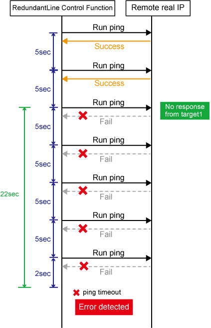
In GS linkage mode, issue the ping command for the real IP address of a target that you set with the remote host monitoring function and for the physical IP address of another node of the cluster. The time it takes for an error to be detected is as follows. Note that if the target detects an error first, it will determine that an error has occurred on the transfer route without waiting for the error detection by ping monitoring. The settings for the error detection time can be changed by using the "hanetobserv param" command. For more details on how to make settings, see "7.15 hanetobserv Command".
Error detection time:
Error detection time = monitoring interval(in seconds) X (monitoring frequency - 1) + ping time out period(*1) + (0 to monitoring interval (in seconds)) |
*1: If the monitoring interval is 1 second, ping time out period would be 1 second, otherwise, ping time out period would be2 seconds.
The default value would look like the following.
5 sec x (5 time - 1) + 2 sec + 0 to 5 sec = 22 to 27 sec
Figure 3.23 Transfer route error detection sequence
Information
Ping monitoring is performed at regular intervals (in seconds). The maximum interval of time required between the time the monitoring destination fails and the time the next ping is sent. Therefore, it takes at least 22 seconds and up to 27 seconds to detect the failure after a failure has occurred.
If applications monitor the network, configure the monitoring time so that an error should not be detected before GLS changes the route.
Just after starting error monitoring for transfer routes, or switching recovery monitoring to error monitoring, error detection will be pended until the waiting time for linkup elapses.
This section describes the transfer route recovery detection sequence.
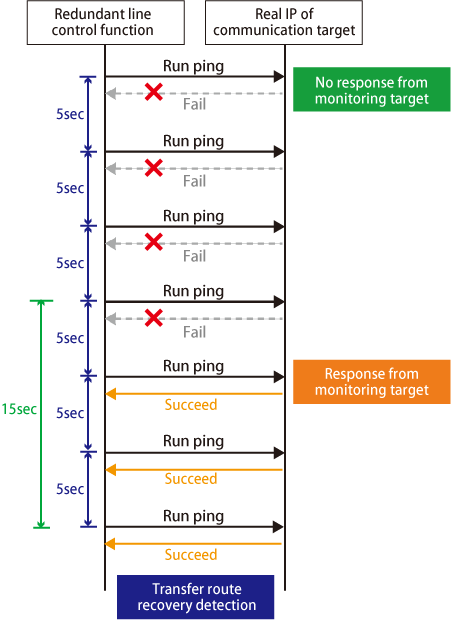
In GS linkage mode, issue the ping command for the real IP address of the target that you set with the remote host monitoring function. After the transfer route error has been detected, GLS performs recovery monitoring by ping to monitor the state of the recovery of the GLS transfer route. The time it takes for recovery to be detected is as follows. Note that if the target detects the recovery first, it will determine that the transfer route has recovered without waiting for the recovery detection by ping monitoring. The settings for the error detection time can be changed by using the "hanetobserv param" command. For more details on how to make settings, see "7.15 hanetobserv Command".
Recovery detection time:
Recovery detection time = recovery monitoring interval (in seconds) + recovery monitoring interval (in seconds) x retry count (count) + (0 to recovery monitoring interval (in seconds)) |
The default value would look like the following.
5 sec x 0 time + 0 to 5 sec = 0 to 5 sec
When the retry count is 2 times, the value would look like the following.
5 sec x 2 time + 0 to 5 sec = 10 to 15 sec
Figure 3.24 Transfer route error detection sequence (Retry count (2 times))
