This section explains the network parameter auto-configuration function for cloning images.
Defining public LAN network parameters for each managed server before collecting cloning images enables automatic configuration of the cloned servers' public LAN network interfaces when later deploying those cloning images.
This speeds up the deployment of multiple servers, as public LAN IP addresses no longer need to be manually and separately configured on each cloned server.
To use this feature, the following settings must first be defined:
When not using LAN redundancy
IP address
Subnet mask
When using LAN redundancy [Linux]
The "NIC switching mode (Physical IP address takeover function)" of PRIMECLUSTER Global Link Services
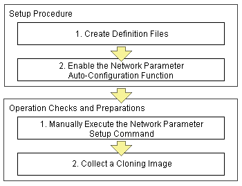
Figure 8.2 Setup Procedure When Using the Network Parameter Auto-configuration Function

Note
[Windows/Linux]
The network parameter auto-configuration function cannot be used on the admin LAN. If used, deployment commands may fail when deploying new servers may fail, or communication issues may occur during collection or deployment of cloning images.
[Linux]
When using LAN redundancy, cancel any network redundancy settings that were made on managed servers using PRIMECLUSTER Global Link Services before deploying new servers.
If not cancelled, deployment commands may fail when deploying new servers. Moreover, the manually set redundancy configuration will be automatically cancelled during the cloning process. This may cause communication issues during the execution of deployment commands, or the collection of cloning images.
Once the deployment of new servers has completed, redundancy network configurations (for the admin LAN or other networks) that are not handled by the network parameter auto-configuration feature should be set up manually.
PRIMECLUSTER Global Link Services cannot be used to enable admin LAN redundancy on servers running SUSE Linux Enterprise Server or Oracle Enterprise Linux operating systems.
Setup Procedure
Use the following procedure to set up network parameters for a public LAN:
Point
Using a specific managed server (reference server) to collect and update cloning images is recommended in order to centrally manage the network parameters definition files.
Create Definition Files
This section explains how to setup the following definition files.
FJSVrcx.conf
ipaddr.conf
Create those definition files under the following folder on the reference server:
[Windows]
Installation_folder\Agent\etc\FJSVrcx.conf
Installation_folder\Agent\etc\ipaddr.conf
[Linux]
/etc/FJSVrcx.conf
/etc/opt/FJSVnrmp/lan/ipaddr.conf
admin_LAN=192.168.1.11 |
admin_LAN
Enter the IP address used by the reference server on the admin LAN.
hostname
Enter the physical server name of the reference server.
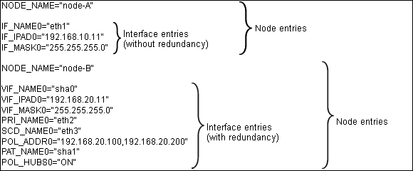
The definition file is made up of the following entries:
One or more node entries
One or more interface entries (with or without redundancy) under each node entry
Figure 8.3 Sample configuration of the definition file (ipaddr.conf)

Refer to the following sample file for details of how to set the definition file (ipaddr.conf).
[Windows]
Installation_folder\Agent\etc\ipaddr.sample
[Linux]
/etc/opt/FJSVnrmp/lan/ipaddr.sample_en
Note
Blank characters and comment lines (lines starting with a comment symbol (#) are ignored.
The expected content of each entry is explained below.
Node Entries
The following table explains the how to define each node entry.
Setting | Keyword | Expected Value | Description |
|---|---|---|---|
Managed server name | NODE_NAME | Physical server name | Physical server name that was set when registering the server. |
Note
Specify additional entries for any node (server) that may be added in the future (one entry per server).
Interface Entries (without redundancy)
The following table explains how to define each interface entry.
Keywords for interface entries should be appended with a number between 0 and 99.
Note
The number appended to each entry's keyword should start with 0 and increase incrementally.
Setting | Keyword | Expected Value | Description |
|---|---|---|---|
Interface name | IF_NAME | Interface name | Specify the interface name as displayed by the operating system (*1) (*1) |
IP address | IF_IPAD | IP address in xxx.xxx.xxx.xxx format | - |
Subnet mask | IF_MASK | Subnet mask in xxx.xxx.xxx.xxx format | - |
*1: As Windows allows interface names to be changed, ensure that the names defined here match those displayed in Windows.
Interface Entries (with redundancy) [Linux]
The following table explains how to define each interface entry.
Keywords for interface entries should be appended with a number between 0 and 99.
This setting uses the "NIC switching mode (Physical IP address takeover function)" of the PRIMECLUSTER Global Link Services product, which requires a virtual interface set with its own IP address.
Within a same node entry, it is possible to define interface entries both with and without redundancy settings as long as interface names differ.
Note
The number appended to each entry's keyword (including both entries with and without redundancy settings) should start with 0 and increase incrementally.
When there is a mixture of interfaces with and without redundancy, assign values in ascending order to the interfaces without redundancy as well.
Interface entries with redundancy settings are only activated with Linux. With Windows, these interface entries will be ignored.
Setting | Keyword | Expected Value | Description |
|---|---|---|---|
PRIMECLUSTER GLS virtual interface name | VIF_NAME | shaX | X is an integer between 0 and 255. |
IP address specified for virtual interface | VIF_IPAD | IP address in xxx.xxx.xxx.xxx format | - |
Subnet mask | VIF_MASK | Subnet mask in xxx.xxx.xxx.xxx format | - |
Name of primary interface | PRI_NAME | Interface name (ethX) | X is an integer equal to or greater than 0. |
Name of secondary interface | SCD_NAME | Interface name (ethY) | Y is an integer equal to or greater than 0. |
IP address of monitored destination | POL_ADDR | IP address in xxx.xxx.xxx.xxx format | Up to two IP addresses can be specified, separated by a comma. |
Virtual interface name for standby patrol | PAT_NAME | shaY | Y is an integer between 0 and 255. |
Hub-to-hub monitoring ON/OFF | POL_HUBS | ON/OFF | Specify "ON" to enable hub-to-hub monitoring, or "OFF" otherwise. |
Refer to the PRIMECLUSTER Global Link Services manual for details on each setting.
Enable the Network Parameter Auto-Configuration Function
Enable the network parameter auto-configuration function by executing the following command:
Execute this command from a managed server.
[Windows]
>"Installation_folder\Agent\bin\rcxadm" lanctl enable <RETURN> |
[Linux]
# /opt/FJSVrcxat/bin/rcxadm lanctl enable <RETURN> |
For details on this command, refer to "5.5 rcxadm lanctl" of the "ServerView Resource Coordinator VE Command Reference".