
| PRIMECLUSTER Global Link Services Configuration and Administration Guide: Redundant Line Control Function 4.2 (for Linux) |
Contents
Index
 
|
| Chapter 3 Environment configuration | > 3.7 Configuring other functions | > 3.7.2 Transfer route multiplexing with Tagged VLAN interface |
When using a tagged VLAN interface on NIC switching mode, specify the tagged VLAN interface instead of a physical interface at configuration.
In addition, when tagged VLAN interfaces on the same physical network cable is made redundant by two or more virtual interfaces, the mode to "synchronous switching" or "asynchronous switching" operation is defined. Below, operation of "synchronous switching" and "asynchronous switching" is explained.
|
Redundant network methods |
Switchover |
||
|
Synchronous |
Asynchronous |
||
|
NIC switching mode (Logical IP takeover) |
IPv4 |
Enabled |
Enabled |
|
IPv6 |
Enabled |
Enabled |
|
|
Dual |
Enabled |
Enabled |
|
|
NIC switching mode (Physical IP takeover) |
IPv4 |
Disabled |
Enabled |

For configuration of monitoring target, refer to "7.7 hanetpoll Command".
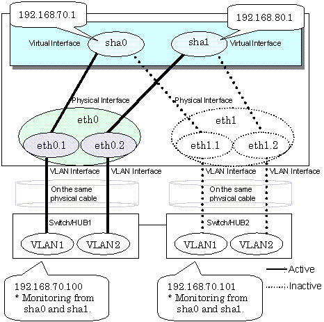
In two or more virtual interfaces which bundle multiple tagged VLAN interfaces redundantly, by defining the same monitoring target IP address, all virtual interfaces are synchronous switching, when failure occurs in monitoring of transfer path. When the switch/HUB of a monitoring target has only one IP address, "synchronous switching" of a virtual interface is chosen.
Figure 3.8 illustrates of synchronous switching architecture.

In the above figure, sha0 and sha1 of the network interfaces monitor the same IP address. If a transmission route failure is detected on sha0, virtual interface switching of sha1 as well as sha0 will occur,
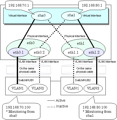
Two or more virtual interfaces that bundle the tagged VLAN interface can be asynchronously switched. In this case, the monitoring target IP address from which it differs for every virtual interface is defined as monitoring target information. When two or more definitions of the IP address are possible to switch/HUB used as a monitoring target, the asynchronous switching of the virtual interfaces is chosen to use Standby NIC effectively.
Figure 3.9 illustrates of asynchronous switching architecture.

In the above figure, sha0 and sha1 of the network interfaces monitor the different IP addresses respectively. If a transmission route failure is detected on sha0, and virtual interface switching of sha0 occurs, that of sha1 will not occur.

Contents
Index
 
|